IR_remote_MQTT_MATLAB
Project progress report on 10/28/2022
1. Using Arduino IR remote library for getting a raw data
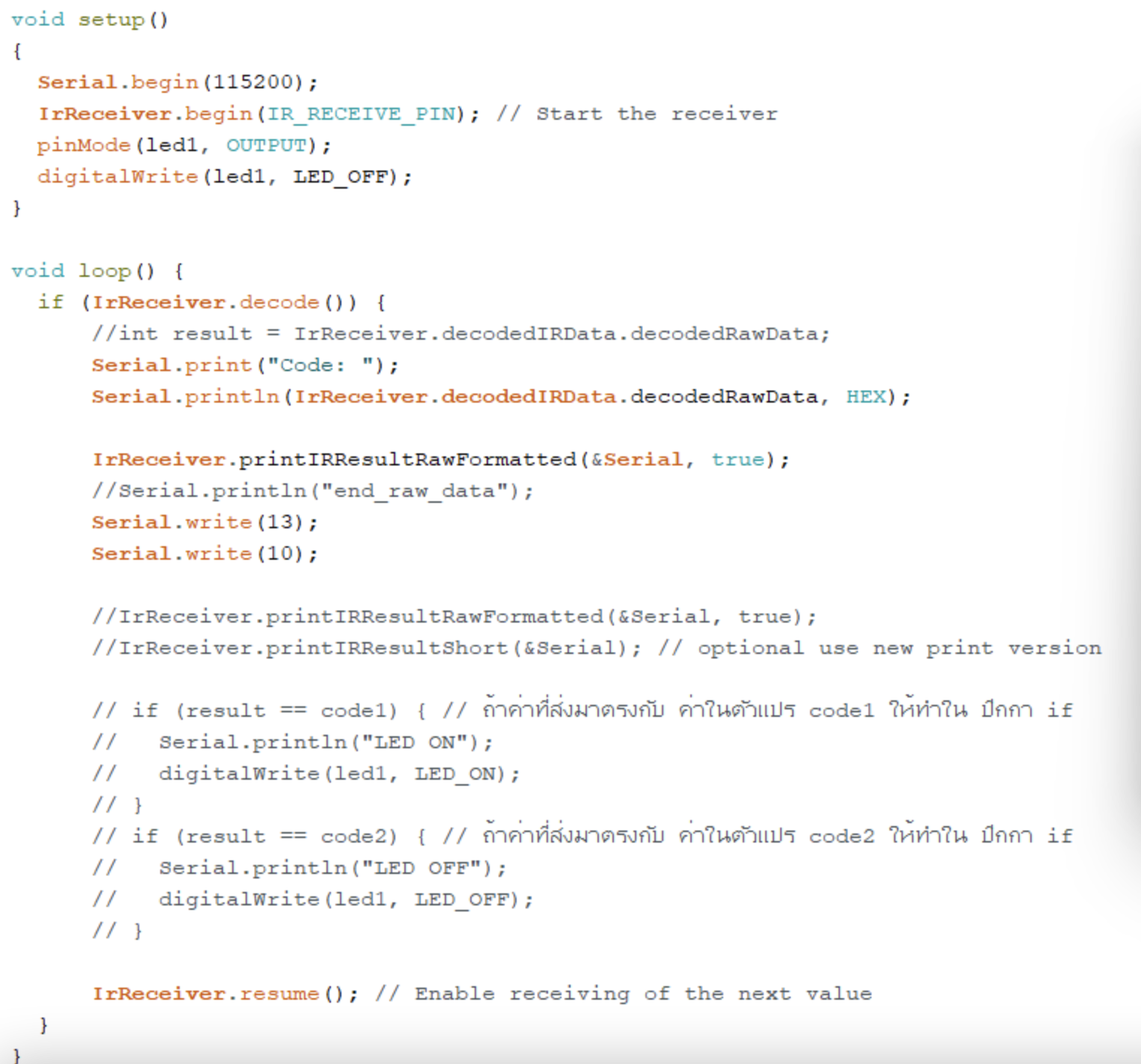
We begin the IrReceiver pin with:
Ir.Receiver.begin( PIN );
We check for received data with:
if (IrReceiver.decode()) {}
then we start with printing the first line in serial port monitor. we want string sentencen “Code: (Hexadecimal Code) “ in first line.
Serial.print("Code: ");
Serial.println(IrReceiver.decodedIRData.decodedRawData);
After we get the Hexadecimal code in first line , we want a timestamp of IR reciever data so
Ir.Receiver.printIRResultRawFormatted(&Serial,true);
Serial.write(13); //used CR/LF system
Serial.write(10);
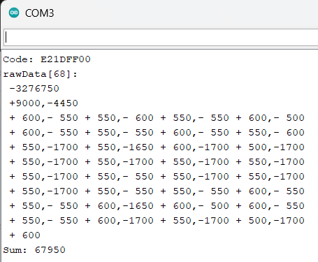
finally we will get a Hexadecimal code and timestamp in serial port like this
reference: IR arduino library: https://github.com/Arduino-IRremote/Arduino-IRremote
2. Sending a raw data with arduino serial port to MATLAB (testing in matlab live script)
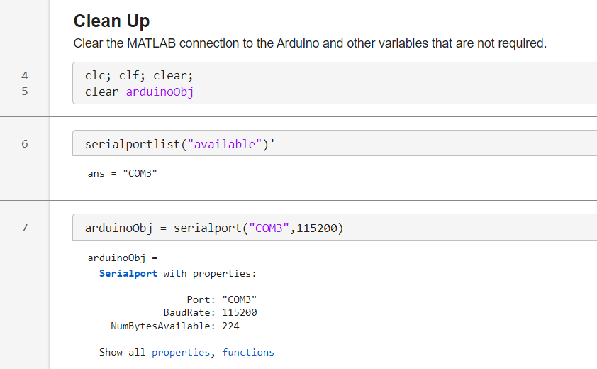
2.1 clear everything in matlab command window and clear arduino serial port for matlab
clc; clf; clear;
clear arduinoObj
2.2 create a arduino class obj with COM3 and 115200 rate bit per second .
serialportlist("available"); %list a serial port that is available for us is COM3 .
arduinoObj = serialport("COM3",115200)
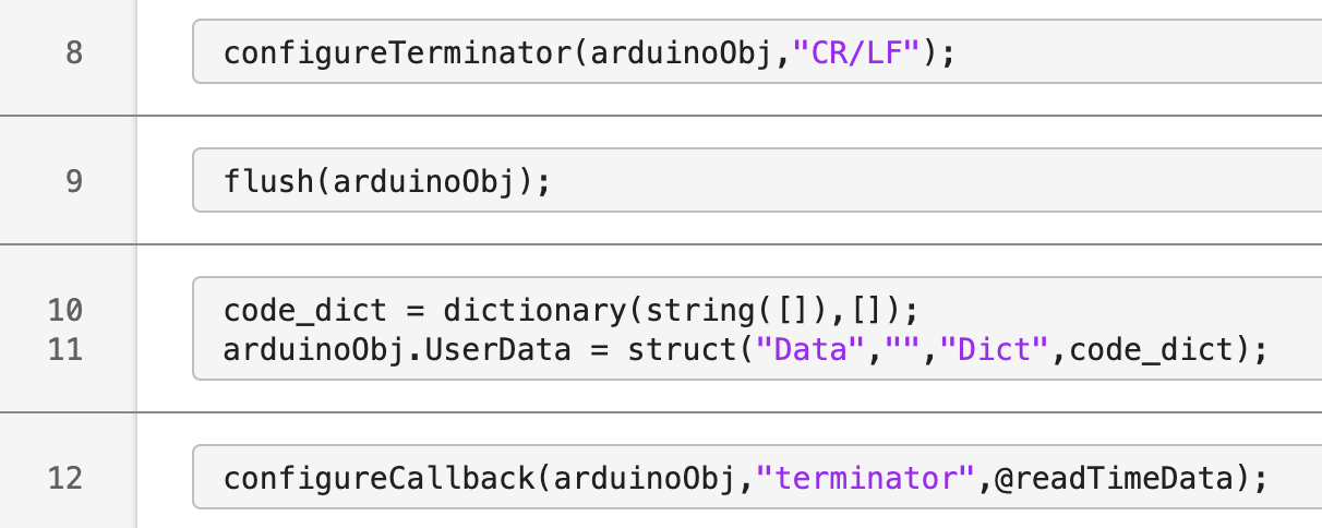
2.3 config a type of serial terminator and Callback readtimeData function to transform a raw_data from arduino serial monitor. (Because matlab print each one by one single line in serial monitor so we need to transform a data that come in single line of serial monitor )
configureTerminator(arduino0bj,"CR/LF");
configureCallback(arduinoObj,"terminator",@readTimeData);
3. Getting only timestamp from rawdata .
start creating a readTimeData to transform a string data to int data time stamp.

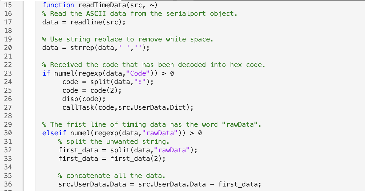
3.1 matlab read one by one of line in serial monitor and collect it in variable name “data” and excute the space of string .
data = readline(src);
data = strrep(data,' ','');
3.2 first line in serial monitor is string sentence “Code: (Hexadecimal Code) “ so we detect string “Code” with regexp(“Code”) after that we split a string with “:” then we will get a string array [Code , (Hexadecimal Code)] then we want only hexadecimal code so we will select only the second one (index = 2) and collect it with variable name “code”.
if numel (regexp (data, "Code")) > 0 %first line case
code = split(data,
":") ;
code = code (2) ;
disp (code) ;
callTask(code,src.UserData.Dict);
3.3 the second line in serial monitor is string sentence “rawData[]: ….” so we detect string “rawData” like the first line but keep in variable in arduino class name “Data” (src.UserData.Data). This is the time stamp part .
elseif numel (regexp (data, "rawData") ) > 0  %second line case
first_data = split (data, "rawData");
first data = first data(2);
src.UserData.Data = src.UserData.Data + first data  %concatenate all the data.
else % other case
sc. UserData. Data = src. UserData.Data + data:
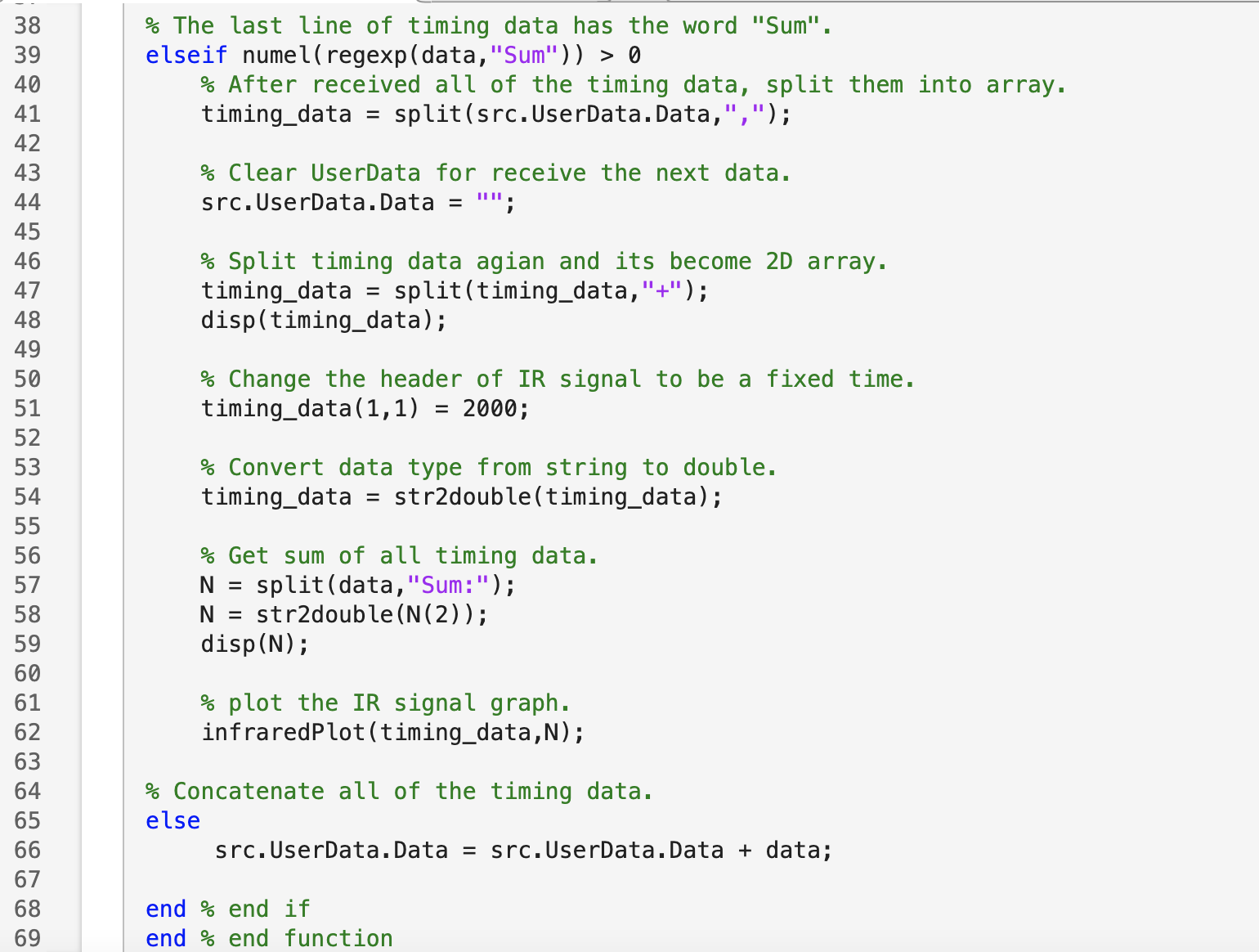
3.4 the next line in serial port will be the step that concatenate a string until the line that have a word “Sum”. if that line have Sum it is the last sentence of time stamp in serial monitor so we start split by string “,” so we will get an 1D string array of timestamp number then next we execute the space each members in array . Next step we split a string “+” each member in string the each member in 1D array will be 1D array that have 2 member then our 1D string time stamp array now become 2D array with 2 columns and (amount of member of old 1D timestamp array ) . after that change it to number string then plot a graph by infaredPlot function.
elseif numel (regexp (data, "Sum") ) > 0    % last sentence case
timing_data = split(src.UserData.Data,",");             % After received all of the timing data, split them into array.
src.UserData.Data = "";                                 %Clear UserData for receive the next data.
timing_data = split (timing_data,"+");                  % Split timing data agian and its become 2D array.
disp(timing_data);
timing_data(1,1)   = 2000;                              % Change the header of IR signal to be a fixed time.
timing_data = str2double(timing_data) ;                 % Convert data type from string to double (int).
N= split(data, "Sum:") ;                                % Get a sum of timing stamp
N= str2double (N(2)) :
disp(N);

infraredPlot (timing data,N) ;                           % plot the IR signal graph
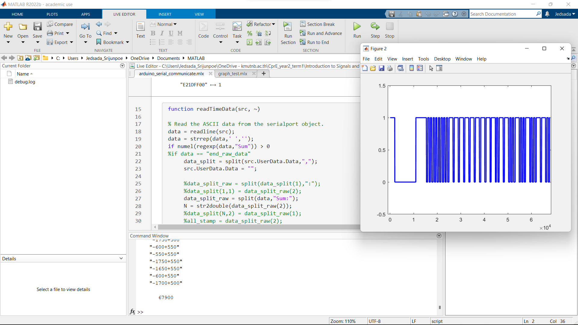
4. implement matlab code in live script for plotting IR pulse from timestamp .
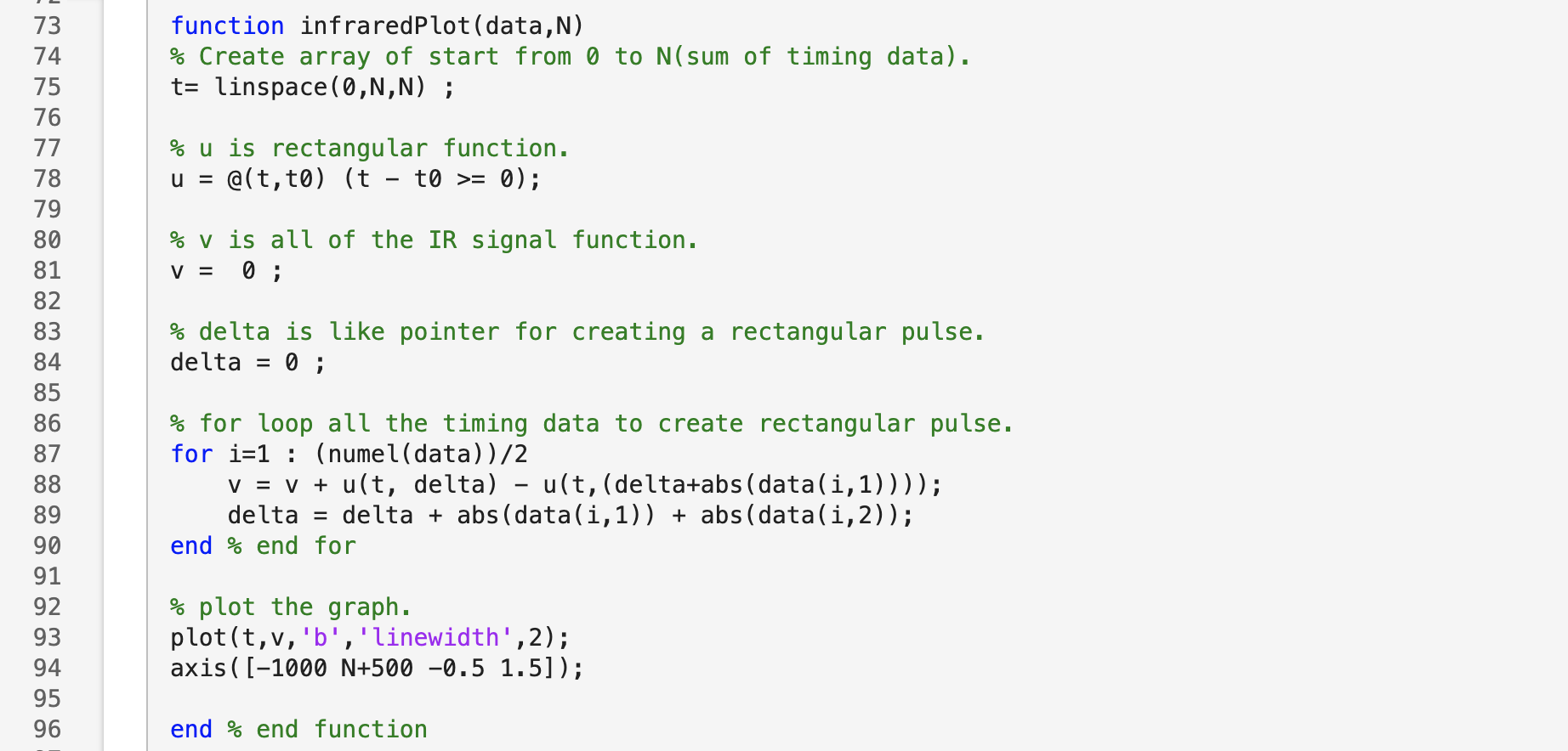
start creating plot graph function name “ infaredplot “ with required to 2 parameter number timestamp array and number of sum of timestamp .
the graph will represent IR from remote in sum of square pulse that have different time shift from time stamp array .
4.1 first we start create a array of t start at 0 to N with N samples.(N is the sum of time period in time stamp) and create a unitstep function ( not a symbolic )
4.2 next we use for loop to sum square pulses that shift by time in timestamp array and in the end of loop we get a function of summing of square pulse .
